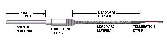
Mineral Insulated Thermocouples with Lead Wires
(Series TL1)
Ordering Information
Configure this style to request a quote or call for assistance
Part No.:
select options
Start Here
| 1 Series |
2 Calibration |
3 Sheath Diameter |
4 Sheath Material |
5 6 Sheath Length |
7 Junction |
8 Transition Fitting |
9 Lead Wire Material |
10 Lead Wire Length |
11 Termination Style |
12 Special Features |
13 Attached Fitting |
14 15 Insertion Length |
|---|---|---|---|---|---|---|---|---|---|---|---|---|
| TL1 |
| 2 | Calibration |
|---|---|
| J | Type J |
| K | Type K |
| T | Type T |
| E | Type E |
| W | Type J (Special limits) |
| X | Type K (Special limits) |
| Y | Type T (Special limits) |
| Z | Type E (Special limits) |
| 3 | Sheath Diameter |
|---|---|
| A | 0.032" (0.8mm) |
| B | 0.040" (1mm) |
| C | 0.059" (1.5mm) |
| D | 0.062" (1.6mm)(1/16") |
| E | 0.079" (2mm) |
| F | 0.092" (2.3mm) |
| G | 0.118" (3mm) |
| H | 0.125" (3.2mm) (1/8") |
| J | 0.156" (4mm) |
| K | 0.177" (4.5mm) |
| L | 0.188" (4.8mm) (3/16") (standard) |
| M | 0.236" (6mm) |
| N | 0.250" (6.4mm) (1/4") |
| P | 0.314" (8mm) (5/16") |
| Q | 0.375" (9.5mm) (3/8") |
| Sizes for reference only (Standard tolerances apply) | |
| For other diameters consult factory |
| 4 | Sheath Material |
|---|---|
| F | 304 SS |
| H | 316 SS |
| M | INCONEL (600) |
| N | 446 SS |
| P | 310 SS |
| Q | Hastelloy |
| R | Pyrosil D |
| 5 6 | Sheath Length |
|---|---|
| ¼-600 |
| 7 | Junction |
|---|---|
| G |  Grounded (Single)
 |
| U |  Ungrounded (Single)
 |
| E | 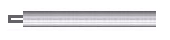 Exposed (Single)
 |
| R |  Exposed & recessed (Single)
 |
| W |  Grounded (Dual)
 |
| X |  Ungrounded & isolated (Dual)
 |
| Y | 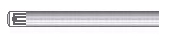 Ungrounded common (Dual)
 |
| Z |  Expose & isolated (Dual)
 |
| Ungrounded and isolated only available in 0.156" OD & larger |
| 8 | Transition Fitting |
|---|---|
| 1 | |
| 2 | |
| 3 | |
| 4 | |
| 5 | |
| 6 | |
| 7 | |
| 8 | |
| 500°F epoxy standard | |
| See special features for ceramic potting |
| 9 | Lead Wire Material |
|---|---|
| A |  Fiberglass (800°F)
 |
| B |  Fluoropolymer (400°F)
 |
| C |  Polyimide (500°F)
 |
| D |  PVC (220°F) PVC (220°F) |
| E |  High temperature fiberglass (1200°F)
 |
| F |  Fiberglass with stainless steel braid (800°F)
 |
| G |  Fluoropolymer with stainless steel braid (400°F)
 |
| H |  Fiberglass with armor cable (800°F) Fiberglass with armor cable (800°F) |
| J |  Fluoropolymer with armor cable (400°F)
 |
| K |  Polyimide with armor cable (500°F)
 |
| L |  High temperature fiberglass with armor cable (1200°F)
 |
| M |  Fiberglass with stainless steel braid with armor cable (800°F)
 |
| W |  Fluoropolymer with stainless steel braid with armor cable (400°F)
 |
| X |  High temp fiberglass with ss steel braid (1200°F)
 |
| Wire gauge determined by ECS based on sheath diameter |
| 10 | Lead Wire Length |
|---|---|
| 6-999 | |
| Over 999" contact factory |
| 11 | Termination Style |
|---|---|
| A |  2" stripped leads (bare ends)
 |
| B |  2" stripped leads w/ spade lugs
 |
| C |  Standard male plug (400°F)
 |
| D |  High temp male plug (660°F)
 |
| E |  Max temp male plug (800°F)
 |
| F | 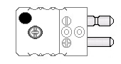 Ceramic male plug (1200°F)
 |
| G |  Solid pin plug
 |
| H |  Standard female jack (400°F)
 |
| J |  Miniature plug (400°F)
 |
| K |  Miniature jack (400°F)
 |
| L |  2" stripped leads w/ #6 Ring terminals
 |
| N |  Standard 3 pin plug w/ ground wire (400°F)
 |
| P | 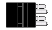 Dual molded male plug (400°F)
 |
| W |  2” stripped leads w/ pin terminals
 |
| Q |  2” stripped leads w/ wire ferrules
 |
X |
 Extra long lead wire length (beyond 2” stripped leads)
 |
| 12 | Special Features |
|---|---|
| None | |
| 47 |  Stranded conductor (Lead wire)
 |
| 04 |  Flat tip probe
 |
| 07 |  Cable Clamp
 |
| 08 |  Bx Connector
 |
| 09 |  Mating connector
 |
| 10 |  Armor cable adapter
 |
| 11 |  International IEC 584-3 color coded leads
 |
| 12 |  British color coded leads
 |
| 13 |  German color coded leads
 |
| 14 |  Japanese color coded leads
 |
| 15 | Reverse polarity color coded leads |
| 16 |  French color coded leads
 |
| 18 |  Moisture protection boot on connector
 |
| 19 |  High temperature ceramic potting (1200°F)
 |
| 21 |  Fluoropolymer coated armor cable (Fluoropolymer)
 |
| 24 |  Fluoropolymer covered probe
 |
| 25 | 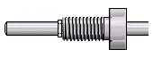 Free spinning fitting (held on probe by a crimp ring)
 |
| 28 |  90 degree bend
 |
| 30 |  45 degree bend
 |
| 13 | Attached Fitting (optional) |
|---|---|
| None | |
| F01 |  1/8" npt single thread
 |
| F02 |  1/4" npt single thread
 |
| F03 |  3/8" npt single thread
 |
| F04 |  1/2" npt single thread
 |
| F05 | 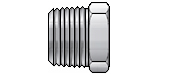 3/4" npt single thread
 |
| F06 |  1/2" npt x 1/2" npt double thread
 |
| F07 |  1/2" npt double thread. Spring loaded
 |
| F08 |  1/2" npt x 1/2" npt double thread. Spring loaded w/ oil seal
 |
| F09 | 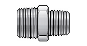 1/2" npt x 3/4" npt double thread
 |
| F10 |  3/4" npt x 3/4" npt double thread
 |
| F11 | 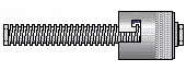 Fixed bayonet cap assembly
 |
| F14 |  1/2" npt x 1" npt double thread
 |
| F15 |  1" npt single thread
 |
| F16 |  Adjustable 7/16" ID bayonet cap fitting (1/8" OD & 3mm OD)
 |
| F17 | 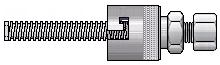 Adjustable 12.5mm ID double slot bayonet cap fitting (1/8" OD & 3mm OD)
 |
| F18 |  1/8" npt compression fitting (Brass)
 |
| F19 |  1/8" npt compression fitting (Stainless Steel)
 |
| F20 |  1/4" npt compression fitting (Brass)
 |
| F21 |  1/4" npt compression fitting (Stainless Steel)
 |
| F22 |  1/2" npt compression fitting (Brass)
 |
| F23 |  1/2" npt compression fitting (Stainless Steel)
 |
| F28 | 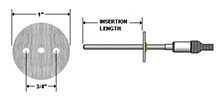 1" circular mounting flange
 |
| For other fittings not shown contact factory |
| 14 15 | Insertion Length (when required) |
|---|---|
| None | |
| 1-144 |
- Solid wire is standard on MGO extension thermocouples
- For stranded wire see special features
